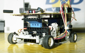
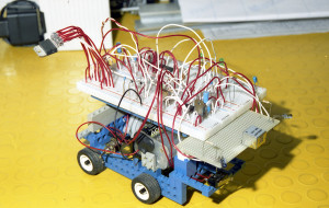
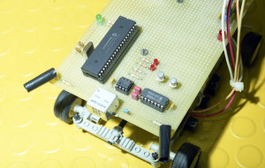
My personal interpretation of the classic walker BOT. 4 wheels, 2 steering in a mixture of LEGO, screws and glue. Something completely different from the commercial template like floors scrubbing robot.
The name of the Bot derives from a dialect term for Italian province of Lazio (a region of central Italy). ”Jubbo” refers to a “inexpert young” who should be trained to perform at his job better. ![]()
Before starting to build a small Bot, we must be able to drive at least the most simple and common type electric motor.
Certainly in the case of an application with the most stringent requirements, the use of a stepper motor is a correct solution. But in this project I tried not to use it. In the case of a new version … I think I will use stepper motors.
The brushed DC motor.
A brushed DC motor is an internally commutated electric motor designed to be run from a DC power source. If you do not remembered well the operation … this wonderful article on Wiki is for you. ![]() DC Motor
DC Motor
The most effective driver for a DC motor is a circuit called H-bridge.
Building the H-Bridge
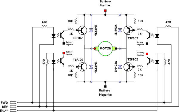
Schematic for the bridge is shown below.
The fast recovery diodes (shown in light blue) are optional when you are using the TIP102/107 as those transistors have a diode built into them. However you can include them for greater protection at higher currents. You will note that I also take advantage of the symmetrical nature of the bridge by using resistor packs rather than individual resistors. These packs allow for a tighter design while still using through hole technology. If size is an issue, you’ll probably go with surface mount rather than this type of circuit.
Parts List for the Simple H-Bridge :
2x TIP107 TIP107, PNP Power Darlington Transistor (TO-220AB)
2x TIP102 TIP102, NPN Power Darlington Transistor (TO-220AB)
1x 4608X-102-10K 10K Ohm, SIP Resistor network (independent resistors)
1x 4608X-102-560 560 Ohm, SIP Resistor network (independent resistors)
1x 4608X-102-1K 1K Ohm, SIP Resistor network (independent resistors)
1x PS2501-4 Quad Opto-coupler (16 pin DIP)
4x 1N4933 1A Fast Recovery Rectifier (Optional)
In the previous section we discussed the individual parts of this design, here they are gathered together in a single circuit. You should notice that the opto-isolator LEDs are connected to three wires labeled “FWD”, “REV”, and “ENA*.” These wires deserve a bit of explanation.
The FWD, REV, and ENA* lines are the interface between the bridge and the microprocessor. You will notice their is no “ground” signal. When you connect these pins to microcontroller, combinations of 1′s and 0′s on the line turn on different pairs of transistors. The following table lists all possible combinations of input.
FWD REV ENA* Description
1   0   0    Turn on upper left source and lower right sink. (go forward)
1   0   1    Disable lower right sink. When fed a PWM signal the bridge modulates the "forward" current through the motor.
1   1   0    Turn on both lower left sink and lower right sink, shorting the motor. This causes a rotating motor to stop rotating so this mode is called "Braking."
1   1   1    Disable both lower sinks. When fed a PWM signal the bridge modulates the "braking" of the motor.
0   1   0    Turn on the upper right source and lower left sink. (go backward)
0   1   1    Disable lower left sink. When fed a PWM signal the bridge modulates the "reverse" current through the motor.
0   0   0    Turn off all sources and sinks. "Coast" motor is not engaged at all.
0   0   1    Turn off all sources and sinks in a different way, same effect though.
So why go to all this trouble? The interface as designed gives you access to all of the interesting combinations of sinks and sources enable, while not allowing for any “illegal” states. An illegal state in a full quadrant H-bridge (4 inputs, one for each quadrant) is one that turns on the upper source and lower sink on the same side. This combination causes a direct short circuit to be created between the battery terminals (not good!) and usually causes one or both of the transistors that are on to go up in smoke. Just remember not to go above 2.5Khz unless you replace the opto-isolator with a faster one.
IC L298 DUAL FULL-BRIDGE DRIVER
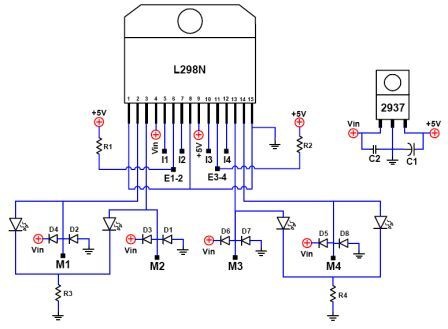
Although it is interesting to build from scratch the circuit, there are commercially available H-Bridge in a single IC. This makes easier design and reduces the spaces. I chose the L298 for my Bot. From datasheet : “The L298 is high voltage, high current dual full-bridge driver designed to accept standard TTL logic levels and drive inductive loads such as relays, solenoids, DC and stepping motors.”
Here is the L298 Datasheet.
This is the typical application for a DC motor. Is used only one of the two full H-bridge available.
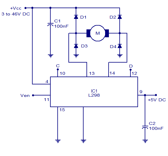 If Ven is low the motor is not engaged at all, whatever the state of C and D. Ven can be the PWM signal for bridge power modulation in forward, reverse and braking mode.
Ven  C    D
0    X    X        Motor is not engaged
1    1    0        Go forward
1    0    1        Go reverse
1    1    1        Braking
The four output lines of the L298 can also be used individually to drive the coils of a unipolar stepper motor.
Bouncing experiments
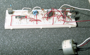
In the design of my Bot, the first thing I wanted to test the efficiency of microcontroller compared to the speed and response time with the following command to the motor driver. So I made the first prototype just control this feature.
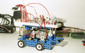 |
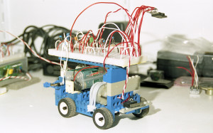 |
Later, I experienced an IR proximity sensors. IR proximity sensors works by the process of triangulation. A pulse of light (wavelength range of 850nm + /-70nm) is emitted and then reflected back (or not reflected at all). When the light returns it comes back at an angle That is dependent on the distance of the reflecting object. Triangulation works by detecting this reflected beam angle. By knowing the angle, distance can then be determined.
I have experimented with different types of IR sensors and I will tell you why IR is NOT the best out there. ![]() Infrared sensors, emit infrared light, and therefore the sensors cannot work accurately outside or even inside, if there is direct or indirect sunlight (but this is not entirely true for Sharp IR sensors, since they will work pretty accurately in ambient light.) So no infrared ranging sensors on your outdoor robot.
Infrared sensors, emit infrared light, and therefore the sensors cannot work accurately outside or even inside, if there is direct or indirect sunlight (but this is not entirely true for Sharp IR sensors, since they will work pretty accurately in ambient light.) So no infrared ranging sensors on your outdoor robot.
Now since light does not reflect the same way off every surface, the infrared sensor reading will be different for different surfaces, different colors, and different shades EVEN if the range is the same. Most of the time this reading is not too off, so the robot can still function.
Conclusion for IR Sensors
Use infrared ranging sensors if :
- You do not care about incredibly accurate ranging
- The sensor will not be used outside in the sun
- You need a narrow beam width
- You want to spend less than €10 per ranging sensor
Next implementation
When I get finally some free time, I will turn to a new design of Jubbot. In this new I want use Ultrasonic Sensors too. The Bot will use both IR and Ultrasound together as they both have different strengths and weaknesses.
Both of them have difficulty with objects that are at an angle as both the sound and the light are reflected off to one side rather than directly back at the sensor. The massive use of microswitch in the focal points of the Bot allows you to unlock situations and cases that were not detected by the sensors.
Finally, the use of a digital micro-camera (as the OV7670) coupled to a controller that deals exclusively to processing of the image, may give good results. I’m looking for an implementation of the algorithms of OpenCV on the micro used.
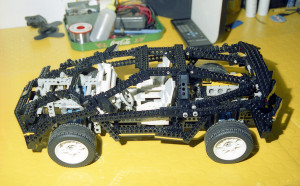
In the next version I want to modify this older model LEGO Technics bought at a sale of a toy store. ![]()
I hope it was interesting. ![]()
Return to home page Home Page

