Microcontrollers based studio
The experiments with the parallel port made me realize that in real life you can not keep busy an entire PC to control the actuators. The natural solution is to use a minimal/embedded system for the direct control of the actuators. The role of the PC is to run a graphical user-friendly application to administer and define the behavior of the embedded system.
Usually this is done through a RS232 serial connection. After downloading the new setting in the controller, PC can be disconnected and normally used with other programs.
This new vision of architecture led me to the advanced use of microcontrollers. I chose to work with the 16F mid-range series from Microchip ®. With the famous PIC16F84, PIC16F876 and PIC16F877.
Common Actuators Board
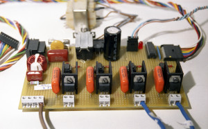
First I just made a new implementation more efficient of previous actuators. I made an independent board common to all control devices.
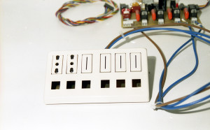
Also in this version, the single independent gate support PWM mode (Dimmer) in addition to full saturation (On/Off). A simple file sockets used to connect the loads to be controlled.
 |
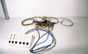 |
I connected only two of the four sockets available because I had no money to buy other sockets. ![]()
The Scheduler
The scheduler was the device with the highest complexity for the firmware. It can be compared to a first rough Rule Engine that performs only as scheduler.
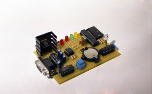
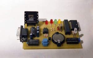
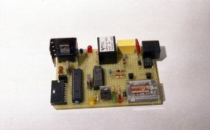
Mounted on the board are visible micro 16F876 and the 24LC256 32K x 8 (256 Kbit) Serial Electrically Erasable PROM. The EEPROM is used to store the DB of schedules entered, instead the internal EEPROM of the micro 16F876 is used to store the operating configurations.
Essential for the scheduler is the presence of a RTC (Real Time Controller). I’ve used the RTC-58321 manufactured by Epson.
Because it is not easy to find its datasheet, I have made available on the site. RTC-58321 Datasheet
Upon power up, the scheduler enters its normal operation. You can not interact with it. You have to have an RS232 serial port configured to 2400bps 8,1, N, and connect it to the board. For the connection of can use a simple flat cable, the serial in the board is already inverted.
A button on board stops operating and enters the scheduler in service mode. On your terminal emulation program you would get:
PicJanus Scheduler Relay Server 1.0
M.E.C. Mazza Emiliano Computing
2000 All Rights Reserved
--->
Trying with the HELP command.
--->HELP
EXIT                                                Exit command system returns in normal mode
HALT                                                Halt command system halts
TURN ALL ON                                         TURN ALL ON command Turns on all gates
TURN ALL OFF                                        TURN ALL OFF command Turns off all gates
STATUS                                              STATUS command displays the states of gates and light sensor
TIME                                                TIME command gets the current time
DATE                                                DATE command gets the current date
TURN ON X                                           TURN ON command turns on a gate
TURN OFF X                                          TURN OFF command turns off a gete
SET DATE GG/MM/YY                                   SET DATE GG/MM/YY command sets a new date
SET TIME HH:MM:SS                                   SET TIME HH:MM:SS command sets a new time
DUMP X                                              DUMP command raw displays of DB (Debug)
ADD SCHED GG/MM/YY HH:MM:SS GG/MM/YY HH:MM:SS X X   ADD SCHED command adds new schedule
CLEAR			                            CLEAR command clears entire DB
LIST SCHED			                    LIST SCHED command displays schedules in DB
DEL SCHED XXXX		                            DEL SCHED command deletes a schedule
DEBUG                                               DEBUG Command (Debug)
In this article, I will not detail the commands of the scheduler. If you’re interested, you can ask me in a post and I will answer in detail.
The Phone controller
The phone controller was the first device used in a real application. A client of mine has to turn on a laser system that was need of at least one hour of heating, before arriving in his laboratory.
Once you’re connected the board to the telephone line as a normal phone (RJ11 connector), the phone controller responds to calls after a configurable number of rings.
After a short jingle the phone controller waits for the texture of DTMF tones corresponding to the requested command. These commands are available:
Command TURN ON [Gate Number] DTMF Texture where G is Gate                * 0 0 1 G #
Command TURN OFF [Gate Number] DTMF Texture where G is Gate               * 0 0 0 G #
Command STATUS DTMF Texture                                               * 0 0 # 0 #
Command HANG UP DTMF Texture                                              * 0 0 # # #
After the command has been correctly recognized a short high frequency sound is emitted, otherwise the sound will be low. The STATUS command emits short tones for each gate. If the tone is high the gate is active, for inactive gates tone will be low. HANG UP sequence disconnect phone and frees the line.
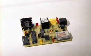
On the board are visible micro 16F876 and the classic DTMF decoder MT8870. In addition to all that is needed to handle the telephone line as the isolating transformer and the switching relay. Remember that ringing signal in the most of the world uses frequencies in 20..40 Hz range and voltage in 40..150 volts range. ![]()
Here is available the MT8870 datasheet. MT8870 Datasheet
The IR controller
In the 80s, home automation was seen as a series of actuators to interact via a remote control similar to that of a television. This controller allows you to use any remote control, including the TV, to control the actuators.
On the board there was a button for programming. Once you have pressed aim the remote to use. On the remote control, press the first button is used to turn on the gate 1, after that to turn it off. Same for the gates 2, 3 and 4.
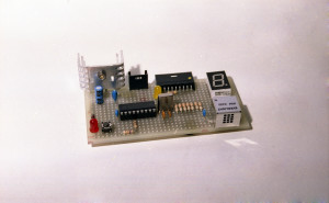
After eight acquisitions, the flashing LED signals the return to the receive mode. The 7 segment display shows which gate you are driving.
That’s all. If you need more explanation of these old projects you can contact me or do it through a post in the blog. I hope it was interesting. ![]()
| Return to home page Home Page |

